Dimensional Tolerances and GD&T for CNC Machining
Dimensional tolerances, are also called linear/size tolerances, they regulate the size of all the dimensions of a design part. While geometric tolerances determine the orientation, location, shape and size of the features of a part.
Geometric tolerances focus on feature tolerances, they don’t provide a complete picture. GD&T stands for the design meaning, it provides a more detailed and over all comprehensive picture of full range of function as well.
What is Geometric Dimensioning & Tolerancing (GD&T)
Geometric Dimensioning and Tolerancing (GD&T) is a language of symbols that are used to describe a part’s nominal geometry and the allow tolerance for variation. The design engineer can concisely define a features location, size, shape and orientation on the part. GD&T is intended as an addition to the coordinate dimensioning system, but not as a replacement.
The function of a part was taken into consideration at the GD&T methodology,
and how that part functions with related parts. Therefore, for proper application of GD&T you need to have understanding of the function of the part within an assembly.
The standards of GD&T have been used throughout the world. The proper application of GD&T is defined within an American Society of Mechanical Engineers (ASME) standard used primarily in the United States and within an International Organization for Standardization (ISO) standard used by many European countries.
What are the advantages of GD&T?
There are many advantages of GD&T, the most important is that it often provides the exact information needed for manufacturers who may not understand the intent of the design. Manufacturers have to know how a part will be functioned in order to produce the best version of that component.
Bellows are the main advantages of the GD&T proceeding:
- Cost can be reduced:
GD&T promotes the accuracy of the designs, that means it allows appropriate tolerances that makes the most effective use for production.
- Enhanced functionality:
It clearly states all design requirements and guarantees the accurate fulfillment of dimensional and tolerance specifications related to the serving purposes of a part.
- Uniformity and convenience:
GD&T is a compatible language among the designers and the manufacturers. It reduces guesswork and misinterpreting designs, and ensures consistency of geometries.
- Accurate communication:
Interpreting designs into physical parts requires accurate and reliable communication. GD&T enables designers, manufacturers and quality teams to communicate clearly with one another, saving time and costs in the process.
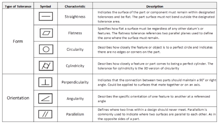
Language of Symbols
In order to properly apply Geometric Dimensioning and Tolerancing (GD&T) you must become familiar with the language of symbols. There are various symbols and types of applied tolerance used in GD&T.
When GD&T is fully utilized it will improve communication between the designer and the mechanist all the way to the shop floor. By using the GD&T established standards, it details your drawings, the design intent can be fully understood by suppliers all over the world. With GD&T you can develop clearly defined designs, taking the function of the part into consideration and allowing for more accurate tolerancing. The quality of your parts will increase and the scrap rate. It eventually results in a win/win situation for the designer and the manufacturer.